“Hello, World!” is often the first step into programming on a PC, a simple tradition that welcomes us to the digital realm. But in the world of microcontrollers, we crave something more tangible—something we can see or touch. That’s where the classic second step comes in: toggling an LED. Let’s bring a little light to our code and make it blink!
The History of LEDs
The journey of the LED began in 1907, when Henry Joseph Round discovered electroluminescence. However, it wasn’t until 1962 that Nick Holonyak Jr., working at General Electric, developed the first practical visible-spectrum LED. Over the years, advancements in semiconductor technology have enabled LEDs to become brighter, more efficient, and available in a wide range of colors. Today, LEDs are ubiquitous, used in devices ranging from indicator lights to sophisticated display panels.
Circuit Diagram
Here’s how to connect the red LED:
- Connect the anode (positive leg) of the LED to ESP32 pin 23 via a resistor.
- Connect the cathode (negative leg) of the LED to a resistor.
- Connect other end of resistor to the ESP32 GND pin.
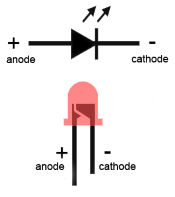
Identifying LED Legs: Positive and Negative
An LED has two legs:
- Positive (Anode): Think of the longer leg as the plus symbol (+). The + has two lines crossing, and if you imagine one line extending straight, it’s longer—just like the positive leg of the LED.
- Negative (Cathode): The shorter leg represents the minus symbol (-), which only has one straight line. Shorter and simpler, just like the negative leg of the LED.
Current Limit Resistor
A resistor is essential when connecting an LED to a microcontroller like the ESP32. Without a resistor, excessive current can flow through the LED, potentially damaging it or the microcontroller.
Choosing the Resistor Value
The resistor value can be calculated using Ohm’s Law:
$$𝑅=(𝑉source–𝑉LED)/𝐼$$
- $𝑉source$: Voltage from the ESP32 GPIO pin (typically 3.3V).
- $𝑉LED$: Voltage drop of the LED (around 2V for a red LED).
- $𝐼$: Desired current (usually $20\,\text{mA}$ or $0.02\,\text{A}$ for standard LEDs).
For a red LED:
𝑅=3.3V–2V0.02A=65Ω
Use the nearest standard resistor value, such as 68Ω or 100Ω, for safety.
What if we don’t use resistor at all which means the resistor value is 0 𝑅=0
Substituting ( R = 0 ):
$$𝐼=(𝑉source–𝑉LED)0$$
This leads to a division by zero, which mathematically implies infinite current. In reality, the current will be limited by:
- The internal resistance of the power source or microcontroller pin.
- The physical breakdown of components like the LED or microcontroller.
If there’s no resistor to limit the current, The LED will attempt to draw as much current as possible. This can lead to Overheating of the LED, causing it to burn out. and Exceeding the GPIO pin’s current limit, damaging the microcontroller.
Without a resistor, the circuit becomes unsafe, leading to damage. A resistor is essential to keep the current within the LED’s and microcontroller’s tolerances.
Basic Blink Code
The pinMode function configures a specific pin on the microcontroller to act either as an input or an output.
- pin: The pin number you want to configure (e.g., LED_PIN).
- mode: The mode to set for the pin. It can be one of the following:
- INPUT: Configures the pin to read input values (e.g., from a button or sensor).
- OUTPUT: Configures the pin to output values (e.g., turn an LED on or off).
The digitalWrite function sets the output state (HIGH or LOW) of a pin that has been configured as an output using pinMode.
- pin: The pin number you want to set the state for (e.g., LED_PIN).
- value: The desired state of the pin:
- HIGH: Sets the pin to a high voltage (typically 3.3V for ESP32 or 5V for Arduino Uno R3 microcontroller), turning on a connected device like an LED.
- LOW: Sets the pin to 0V, turning off the connected device.
Advanced Version (Toggle-based)
the define directives are used to define macros for constants, and these macros are replaced by their values during the preprocessing stage, which happens before the actual compilation. The preprocessor doesn’t perform any validation on these replacements. It simply performs a textual substitution of the defined macro wherever it appears in the code.
This reads whether the pin is currently set to HIGH (on) or LOW (off).
Why You Don’t Need to Explicitly Set pinMode to INPUT Before Using digitalRead?
When the Arduino/ESP32 starts, all GPIO pins are configured as INPUT by default. This means you don’t explicitly need to set a pin to INPUT before using digitalRead().
When a pin is configured as OUTPUT, the pin’s behavior is optimized for driving external devices like LEDs or motors. However, calling digitalRead() on an OUTPUT pin will still work because Arduino internally reads the state of the output register for that pin.
The ! operator negates the value of the current state:
- If digitalRead(LED_PIN) is HIGH, !digitalRead(LED_PIN) becomes LOW.
- If digitalRead(LED_PIN) is LOW, !digitalRead(LED_PIN) becomes HIGH.


