In this project, we’re going to design a smart sunrise alarm that uses a light-dependent resistor (LDR) and an active buzzer. This clever alarm will detect the first light of sunrise and trigger the buzzer to wake you up. Along the way, you’ll also learn the basics of electronics, including the essentials of a Voltage Divider Circuit. Say goodbye to harsh alarms and let nature’s light do the work!
Diagram

Schematics
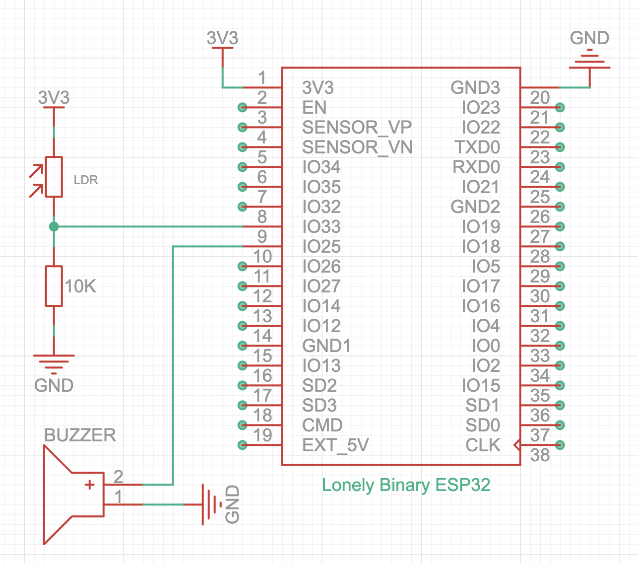
The buzzer’s long leg is positive terminal.
Basic Code
The ESP32 ADC (Analog-to-Digital Converter) allows the microcontroller to read analog voltages and convert them into digital values that can be processed. The ESP32 has 12-bit resolution for its ADC, meaning it can output digital values between 0 and 4095. This means it can read voltage levels between 0V and 3.3V with a range of values in that span (0 – 4095).
This function reads the voltage and returns a digital value corresponding to that voltage. The value will range from 0 (for 0V) to 4095 (for 3.3V). The ESP32 uses its built-in ADC to perform this conversion. ADC is stand for analog to digital convertor which convert the voltage (0-3.3V) to digital (0-4095). The more light the LDR detects, the lower its resistance, which changes the voltage and thus the digital value the ESP32 reads.

The Serial Monitor button is located in the top-right corner of the Arduino IDE. If you see gibberish or unreadable characters in the output, it means the Serial Monitor’s baud rate doesn’t match the baud rate specified in your code.
flowchart LR
  GND --> Resistor --> lightPin --> LDR --> VCC
When you cover the LDR with your hand, the light level drops close to 0. The more light that falls on the LDR, the higher the value will be. In darkness, the LDR’s resistance increases to the megaohm range, effectively blocking the circuit. Since the resistor is connected to GND, the light level reads 0 in the dark.
flowchart LR
  VCC --> Resistor --> lightPin --> LDR --> GND
If you reverse the connection and tie the resistor to VCC instead, the readings will also be reversed.
Sunrise Alarm Code
In the current code, the alarm turns on when the light level exceeds the threshold and stays off otherwise. However, this results in the alarm being active throughout the day, which can become quite annoying.
To improve this, we’ll add a button to dismiss the alarm and put the ESP32 into deep sleep mode for the next 23 hours. It will then wake up just before the next daybreak. Deep sleep mode significantly reduces energy consumption, making it perfect for running the project on battery power.


The button is connected to ESP32 GPIO23, with the other end connected to 3.3V. This means when the button is pressed, GPIO23 will read HIGH. However, when the button is not pressed, GPIO23 is in a floating state, meaning its value could randomly fluctuate between HIGH or LOW.
To avoid this, we need to set a default state for GPIO23 to LOW by using a pull-down resistor. Instead of adding an external resistor, we’ll enable the ESP32’s internal pull-down resistor for GPIO23 by using INPUT_PULLDOWN.
The internal pull-down, pull-up resistor is 45K.
Here is the complete code:
This sets the wake-up timer for the ESP32.
- 23ULL: This specifies the number of hours (23) in an unsigned long long format (to handle large numbers).
- 60 * 60 * 1000000: Converts hours to microseconds because the timer wake-up function requires the duration in microseconds.
This function immediately puts the ESP32 into deep sleep mode, where most components, including the CPU, are powered down to drastically reduce power consumption. During deep sleep, the ESP32 draws only around 20 µA of current. With a standard 18650 battery, this project could last for approximately a year.


